The Build Instructions.


Read the instructions with care. Three (3) times minimum.
Build the buggy in your dreams.
This is just a translation. I'm sure there must be mistakes in it.

Quick Overview and composition drawing:

  1. - Rear-axle (tube AU4G 35x31 L=1000 mm)
  2. - Central frame tube (tube AU4G 35x25 L=420 mm)
  3. - Side frame tube (2 tubes AU4G 35x31 L=700 mm)
  4. - Down tube (tube AU4G 35x31 L=500 mm)
  5. - Legs of front fork (2 tubes AU4G 35x31 L=250 mm)
  6. - Foot pegs (2 tubes AU4G 35x31 L=250 mm)
  7. - Tube horizontal front fork (tube AU4G 35x31 L=250 mm)
  8. - Head downtube / Ballhead (?) (tube AU4G 35x25 L=85 mm)
  9. - Wheel complete from ALROC (Ø 400 x 80 mm / axle Ø 20 mm !!!!)
  10. - Armrest or side support (2 tubes PVC Ø 32 mm L=600 mm)
  11. - Protection Foam (2 foam tubes Ø 80 mm L=500 mm)
  12. - One piece plastic seat
  13. - Spacers front wheel (2 tubes AU4G or stainless steel 27x21 L=20 mm)

The cutting of tubes:


Cut the parts made from the tube of AU4G 35 x 31. The parts which form or are part of: the frame (n°1, 3), the downtube (n°4), the front fork (n°5, 6, 7). See the composition drawing.

Cut the parts made from the tube AU4G 35 x 25. One length of 420 mm (central frame tube n°2) and one length of 85 mm (head downtube, n°8).

Cut 8-10 spacers, used as reinforcements, each 30 mm long, from the tube dural 30 x 26 mm.

  • The rear-axle:

  • 1 - Rear-axle (tube AU4G 35x31 L=1000 mm)
  • a - Hexagonal spacer with thread inside Ø 20 mm L=56 mm
  • b - Steel thread rod Ø 20 mm L=180 mm
  • c - Contra nut stainless steel Ø 20 mm
  • d - Nut with Nylon stop, stainless steel Ø 20 mm

For the assembly of the rear-axle you have to use tube n°1 in which you force on each end the hexagonal spacer n°a. Remove on one side of the hexagonal spacers n°a the sharp edges. The force required deformes the tube. It gets a little hexagonal shaped. Use a rubber hamer or an iron one with a piece of wood in between to prevent deforming n°a. NOTE: "You have only one change. Do it right and force it with care because you migth split the tube n°1 if you do it to wild". Remove sharp edges. At the end the hexagonal spacer n°a is jammed for life in tube n°1.

Cut 2 pieces of the thread rod (Ø 20 mm), each of 180 mm length, n°b. Carefull, don't damage the thread !! Mount them in n°a, use some Lock-Tite if you have it, and fix n°b with a contra nut n°c. Use enough force (and use Lock-Tite). Now slip the 2 slip-on fittings Kee Klamp® 45-6 on the rear-axle. The rear axle is finished when you put both wheels on and secure them with the nut with nylop stop n°d. But you are wiser and only put the nut on, to protect the thread, and leave the wheel until the complete buggy is finished.

The chassis or frame:

  • a - Slip-on fittings Kee Klamp® 45-6
  • b - Reinforcement Tube dural AU4G 30x26 L=200 mm (inside the downtube)

Slip a slip-on fitting Kee Klamp® 45-6 on to the centre of central frame tube (tube n°2, the one which is 5 mm thick) and 1 fitting 45-6 on each end of the tube. Now slip the side frame tubes, n°3, in the end fittings of tube n°2 and the rear-axle. Secure the fittings not to strong. Don't put reinforcements in the tubes at these fittings. They are of no use here. Besides that you want to be able to set the rear-axle more to the back, when needed, which will be difficult with a deformed tube.

Cut a piece of tube, to be used as reinforcement, about 20 cm length of AU4G 30 x 26 mm and put it in the downtube n°4 just before you put it in the centre fitting of tube n°2. The reinforcement tube prevents the downtube from being deformed and allows you to adjust the length of the downtube, in the future, to the length of the driver. Secure the fitting loosely, until final settings.


  • The legs of the front fork:
  • a - Slip-on fitting Kee Klamp® 10-6
  • b - Reinforcements
  • 5 - Leg of front fork (tube AU4G 35x31 L=250 mm)
  • 6 - Foot peg (tube AU4G 35x31 L=250 mm)

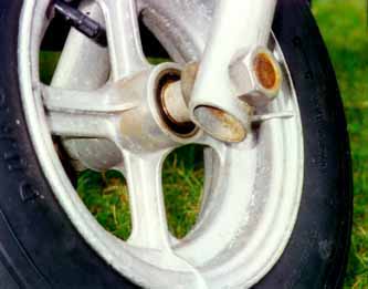
Drill one (1) hole at one (1) end of each front fork leg (tube n°5) with diameter of 20 mm (to attach the front wheel, later). Slip a slip-on fittings Kee Klamp® 10-6 on the other end of the legs (tubes n°5) and also put a reinforcement ring in the tubes.
Slip a slip-on fitting Kee Klamp® 10-6 on one end of each foot peg (tube n°6) and use a reinforcement ring for it. Secure it.
Put the foot peg + reinforcement ring on the frontfork leg, 5 cm under its fiting. Secure it. Now do the other leg and foot peg.


  • The front wheel:
Put a thread rod, minimum length 210 mm (Ø 20 mm) through the sealed ball bearings in the wheel. Now put on each side of the thread rod the following and in this order:
  • 1 spacer 20 mm long of tube dural or stainles steel 27 x 21 mm, Needed to keep the wheel in the centre.
  • 1 stainless steel ring Ø 20 mm
  • 1 leg front fork with 20 mm hole,
    foot peg outside
  • 1 stainless steel nut Ø 20 mm
  • Secure it strong using both nuts until the front form leg starts to deform from round in oval.
  • The downtube head & front fork column:
  • a - Nut with Nylon stop stainless steel Ø 16 mm
  • b - Reinforced vinyl tube 23x15 mm
  • 4 - Downtube AU4G 35x31 L=500 mm
  • d - Fitting Kee Klamp® 10-6
  • 7 - Tube horizontal front fork
    (tube AU4G 35x31 L=250 mm)
  • 8 - head downtube (Ballhead ?)
    (tube AU4G 35x25 L=85 mm)
  • e - Iron spacer inside Ø 16 mm
    (hexagonal filed to a round shape Ø 25 mm)
  • f - Thread rod Ø 16 mm L=160 mm
  • g - Contra-nut stainless steel Ø 16 mm
  • h - Reinforcement rings
  • i - Nut with Nylon stop stainless steel Ø 16 mm

The head of the downtube consists of tube n°8 (AU4G 35 x 25) with a length of 85 mm, in which the round shaped hexagonal n°e (Ø16 mm x 50 mm) can turn around. The diameter of the round filed (a lot of work) hexagonal n°e is just below 25 mm. Thus it fits in tube n°8. It can turn freely without to much margin between them.
Turn a stainless steel nut with Nylon stop n°i, Ø 16 mm, at the end of the stainless steel thread rod n°f, Ø 16 mm and length 160 mm.
Drill a Ø 16 mm hole in middle of tube n°7. Then slide the tread rod n°f through the drilled hole of tube n°7. Put a stainless steel contra nut n°g, Ø 16 mm, on the tread rod n°f. Secure very ligthly. Put the 2 reinforcement rings n°h in tube n°7. Now secure the contra nut n°g with FORCE. Instead of 2 reinforcement rings n°h you could use 1 piece of 70 cm of the tube dural 30 x 26 mm as ONE reinforcement. Don't forget to drill a Ø 16 mm hole in the middle of it.
Turn the round shaped hexagonal n°e on the tread rod n°f until it reaches the contra nut n°g. Slide this into the head of the downtube, tube n°8, until it reaches the contra nut n°g. Now you put on top of the tread rod n°f a piece of reinforced vinyl tube n°b. The length of the vinyl tube is such that, when it is in place, it is a few mm higher then the brim of tube n°8.
Final, secure it with a stainless steel nut with Nylon stop n°a, Ø 16 mm. Note that the vinyl tube will be squezed/deformed.

  • Assemble the front fork:

Slip the last slip-on fitting 10-6, n°d, over the head of the downtube, tube n°8. Secure it with FORCE. Now slip this over downtube n°4. Don't forget to use a reinforcement ring. And to secure it !
Now assemble the previous made legs of the front fork and the horizontal tube n°7. Together they are the front fork. Again don't forget the reinforcement rings. And don't forget to secure it !
With the 2 top slip-on fittings of the front fork legs you can change the caster (angle between the surface and the frontfork seen from the side) for stunt or high speed use. But wait with this until the buggy is finished.

  • The seat:

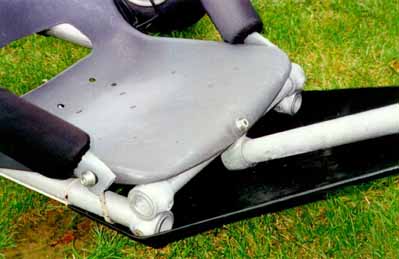
Strip the seat from is legs and
anything else that is of metal.
Only one plastic part is used.


C ut 2 PVC tubes of 600 mm length. Heat the ends and squize them together. Be carefull and don't burn the PVC. The PVC tubes are the arm rests or side support. Put the foam tube over it. The foam tube may be protected by a fabric tube made from dacron or spinakker.
Fix them to the chair with stainless steel bolt/nut Ø 8 mm.

Position the seat on the 3 tubes of the frame (n°2 and °3 and 3). Then fix the seat in the front to tube n°2 with a stainless steel bolt/nut Ø 8 mm and in the back to tube n°3 with seatbelt webbing and a buckle, see drawing.
You can make the seat more solid by putting an extra PVC tube at the high back of the seat and a piece of rope which goes through the arm-rests and the PVC tube to the front of the seat where it is wrapped around and secured to the tubes n°3.
Check the picture below and see that 2 additional holes are drilled in the seat .... the drain.